I am new here, I have a CR Touch which the probe is used as the Z stop switch, but I relised that correct z of it varies so I was thinking If it’s possible to build a firmware with Z stop swicth and CR Touch (BLTouch) ? That way I will get more accurate 0 value otherwise CR Touch will be out of the window soon pointless. I can’t even level is if I Home Z axis 10 times minimum 2 times it gives different 0 point. All my hardware are fully secure gantry etc
I’m also new and just trying to figure out things for myself. I came across your post while trying to figure out how to install, configure, and use the CR Touch on my Ender 3 Max and Ender 3 v2. Have you been able to figure out your leveling issue? Did you still have this issue after enabling Mesh Bed Leveling?
I don’t know what plug etc comes with the CRTouch - but it is 100% BLTouch compatible.
If you have a PROBE port on your mainboard, you really should use that - as the Z-Stop input is usually filtered via a capacitor - which can change the trigger point accuracy. The PROBE port is normally unfiltered and goes directly to the CPU pin.
That being the case, you may have to crimp a new connector onto the cable for the CRTouch to suit - but I don’t know much about this as I’ve never actually seen one.
It will always move up until a G28 / home works correctly.
If you tell the printer to home, it will move the Z axis up slightly, then deploy the probe.
If the probe doesn’t deploy, then it will move up further and try to deploy again. Eventually failing.
If the probe doesn’t deploy, then you need to look at the 3 wire group, if the probe deploys, but doesn’t get detected as deployed, you need to look at the 2 wire group.
You’ll also need to make sure you’re using the PROBE port on the mainboard and not the Z-Stop port.
The probe does not deploy. It flashes purple and red. Then when I leave it alone it continues to flash red.
It is not a physical wiring issue, because the CRTouch worked with base Crealty firmware (I am only upgrading my firmware to Marlin for the BLTouch and Filament Sensor support).
Any ideas? Or for Marlin firmware do I actually need to now switch the wires to a different port on the mainboard?
This is the new motherboard that came in the mail for me (looks like a 4.2.2 version). Now I just need to install it and test the firmware. I will update the results when finished.
UPDATE:
Okay I installed the new motherboard that Crealty sent me.
I am still having an issue with the Z-Probing wizard > Move Z to Home option. The CRTouch probe does not deploy, and it continues to flash red.
So unless this is a wiring issue which I doubt, we can rule out hardware being the issue. This appears to be a firmware issue.
So I will ask again: Is your build compatible with Crealty’s CRTouch device (5 wires and not the BLTouch)? If it is compatible, then what else could be the issue here?
Also my Z-Stop endswitch is NOT installed. Should I put it back?
Attached is a image of the end plug of my CRTouch which goes into the motherboard.
When plugged into the motherboard G V IN G OUT pins, the wire colors meet each pin in the following pattern:
G = WHITE
V = BLACK
IN = YELLOW
G = BLUE
OUT = RED
The same pattern was true when they were plugged into the old motherboard I was using, and both of my 4.2.2 boards have a dedicated probe plug (built in). Judging by the BLTouch FAQ I am assuming that this is what each of the 5 wires are doing:
G = WHITE (Signal)
V = BLACK (Ground)
IN = YELLOW (Signal)
G = BLUE (Ground?)
OUT = RED (5v)
When using Crealty’s official firmware - the CRTouch probe would deploy just fine. However when using your Marlin firmware build, it does not deploy and it continues to flash red.
@CRCinAU is your firmware configured for this type of setup? If I need to switch around my CRTouch wires, what order should the colors be relative to the G V IN G OUT pins?
Here is a video of the CRTouch probe not deploying and flashing red. The Z-Axis does not react to the operation either. It is plugged in correctly as describe by my previous post. All hardware is new.
I’m using the latest build (now with the MarlinUI).
I can’t tell you what the wire colours should be - as the cables can sometimes be different.
I don’t quite understand why your CRTouch isn’t working - as its supposed to be 100% BLTouch compatible.
Are you saying that it works perfectly every time with the stock Creality firmware?
If so, I’m not quite sure what is wrong - I haven’t seen that happen before. Certainly, there haven’t been any reports of that either.
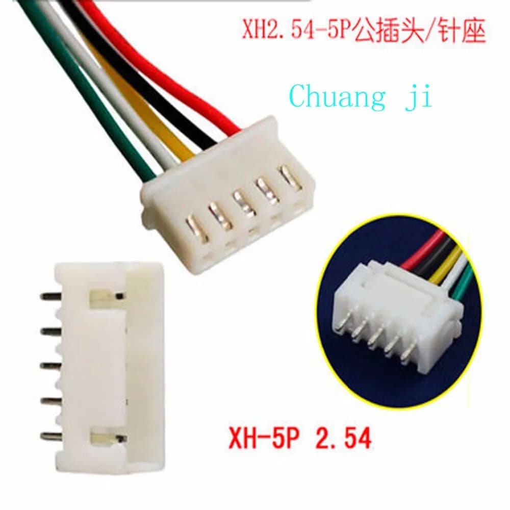
I do note however that the plug on the end of your cable doesn’t quite look like what I’d expect… Is that the right plug for the mainboard? They’re usually an XH2.54 connector. They look like this:
The solution my friend suggested was to flip the wires because maybe one of them wasn’t getting a signal or something.
However the wires cannot be flipped on this plug, they are threaded in.
So I went and bought a BLTouch extension cable, which hopefully had the correct wire configuration:
Long story short - despite asking NUMEROUS questions to the vendor about their wire configuration, and after they assured me it was “correct” and failed to provide vital information about what each color wire represented - after I plugged it in, the first time I turned it on I smelled smoke guess what… so I quickly cut the power.
Motherboard still works, but now the CRTouch isn’t flashing red like in the video it is just dark now.
So I went and bought a BLTouch to replace my CRTouch (imagine that), and after following an install guide and reversing the wires on the Z-Axis its starting to function properly.
I don’t know if I am out of the woods yet (I only started this adventure to have Filament Sensing AND BL/CRTouch compatibility which isn’t in the Creality provided firmware, only in your Marlin builds). I am going to reassemble the printer and make it nice and neat and then continue to test.
I think the reason my CRTouch was not compatible with your firmware, is either because 1) it isn’t or 2) all of my configuration was reversed. But even when I tried to configure it properly, the CRTouch would still not work, even when I tried to use a BLTouch wire on it.
Funny thing is I think I fried my CRTouch when I improperly plugged in the wires, but at least I didn’t make that mistake for my BLTouch.
Anyways its probably safe to mark this as resolved, but it is resolved without any clear answer as to why it wouldn’t work. I would look into it.
thanks for the response, the first one I have received after sending you a message directly and asking for help with help on my BL touch with no response.
this is sort of a rant so I am sorry for hijacking this thread.
As a Noob I too am trying to learn how to write software for my Ender 3 Pro V.2.2 w/BL Touch, the only thing I was trying to find with great difficulty and no success is the “exact” Ender 3 - v4.2.2 Board - BLTouch config and config H files used to create the nightly BIN files. being that they are so close to what i want with exceptions (i.e. BL offset, runout sensor high instead of low) so without trying to start from the beginning using trial and error to figure out. I know that I can load gcode into the Cura file but that is not what I am trying to do.
Well, here’s hoping I can get what I need…H
The probe offset can be changed with the M851 command. It allows you to set the correct offset in your Start G-Code. You don’t need to recompile to change this.
The runout probe is a bit more difficult. However, if you just have the basic microswitch type - you can swap the pins in the plug around to switch it between active low and active high.