The basic:
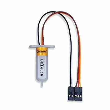
The BLTouch has two parts from a firmware perspective.
a) Control, often called servo. This consists of 3 wires:
- Red is +5v
- Yellow is signal and;
- either a Brown or Black is GND. The control signal is PWM and is treated just like a servo.
b) Trigger. 2 wires:
- Black is GND
- White is the signal.
Wiring the BLTouch to your controller
All mainboards are different but they can have a dedicated bltouch plug - eg the creality V4 series boards
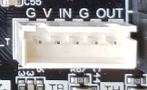
G V and IN are the control pins, G and OUT are the trigger pins.
The board may also have a dedicated probe plug, eg the SKR 1.4. Older boards use servo plugs and endstops plugs.
Creality added a another option the PIn 27 board.
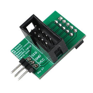
This board plugs into the LCD connector and disconnect the buzzer to use the PWM pin for the bltouch control/servo plug.
NB There are several different type of bltouchs with different wiring. You have to make sure your wiring matches what your board needs. The most common mistake is getting the two pins switched in the 3 pin ‘servo’ cable and letting the smoke out of the mainboard.
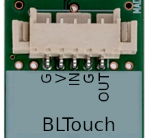
The plug on the BLTouch has the following pinouts:
Firmware Configuration
If you are building your own firmware, you must tell the firmware how you have your BLTouch connected to your mainboard. If you are using a pre-built binary, make sure you understand where it expects your BLTouch to be connected.
-
If your trigger is plugged into the Z_min endstop plugs you must set
#define Z_MIN_PROBE_USES_Z_MIN_ENDSTOP_PIN -
if your trigger is plugged into a dedicated probe port you must make sure:
Z_MIN_PROBE_USES_Z_MIN_ENDSTOP_PINis disabledUSE_PROBE_FOR_Z_HOMINGis enabled.
-
If you’re using a Pin 27 Board you must enable
HAS_PIN_27_BOARDin Configuration.h
Setting your Z-Offset
If you have a normal Marlin mode controller, you can use the Z-Offset Wizard to figure out the correct. Z-Offset. If you have an Ender 3 V2 or similar with a non-Marlin mode display, please refer to this FAQ entry: https://discourse.crc.id.au/t/ender-3-v2-frequently-asked-questions/17#heading--bltouch
Teaching Tech has a great video on the Z-Offset Wizard here:
https://www.youtube.com/watch?v=fN_ndWvXGBQ
Common issues
On power up Bltouch extends and retracts it probe, but wont do it again
This is a issue with the Control/servo plug or configuration. Most conmonly a wiring issues or you have a Pin 27 board and have not told marlin.
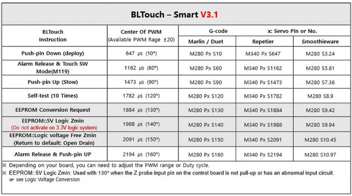
You can test deploying and reacting of the probe with gcodes,
It is also possible you’re not using SERVO0 pin on your controller, in which case you need to tell Marlin which servo the bltouch is plugged into by setting Z_PROBE_SERVO_NR
Probe doesn’t reliably deploy
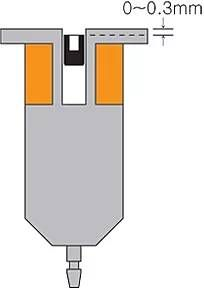
If you command the probe to deploy, but it only does it occasionally, and you’ve checked your wiring and eliminated that as a problem, use a 2.0mm hex key and rotate the internal slug clockwise by 180 degrees. Do not exceed 180 degrees. The maximum indentation between the top of the slug and the flat surface of the BLTouch should not exceed 0.3mm.
Test deployment again to see if there has been a problem in reliability of the BLTouch deploy / stow cycles.
Triggering the BLTouch doesn’t stop the Z axis.
The trigger wires (black and white) have polarity. you must plug it in the correct way. The white cable is on the IO pin and black is on the GND.
Also make sure the firmware is configured to use the dedicated PROBE port instead of the Z endstop or vice versa if you use the Z endstop and not the probe port.
When homing, the probe deploys, retracts, and then the printer shows STOPPED
This is a problem with the return signal coming from the probe to the mainboard. If you have a 5 pin plug, this is the G and OUT pins next to each other, or the separate two pin plug on the 3pin / 2 pin plug combo cables.
Check the polarity of this cable to ensure the probe is triggering the correct pin and that the wires aren’t connected in reverse.